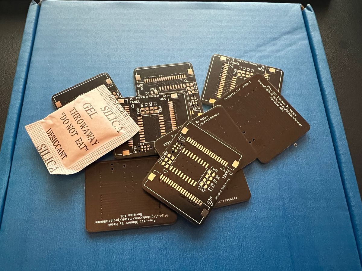
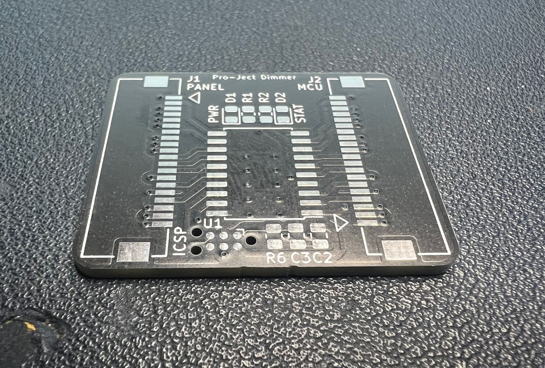
Project Pro-Ject Dimmer PCB
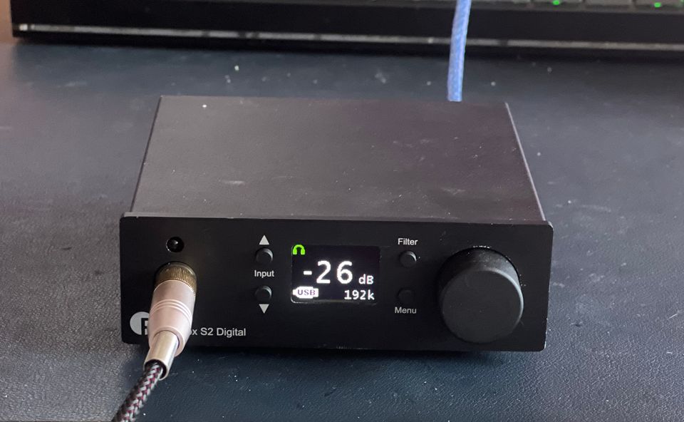
A week later after reverse engineering how the front panel display on the Pro-Ject Pre Box S2 Digital worked and designing an intercept PCB, I have it in my hands.
This blog entry isn't sponsored, but JLCPCB tend to be my go to company for PCB manufacture now - they seem to be cheapest for the size and quantity I want, and their postage options are the most reasonable (assuming you want it in less than a month, but more than a day or two later).
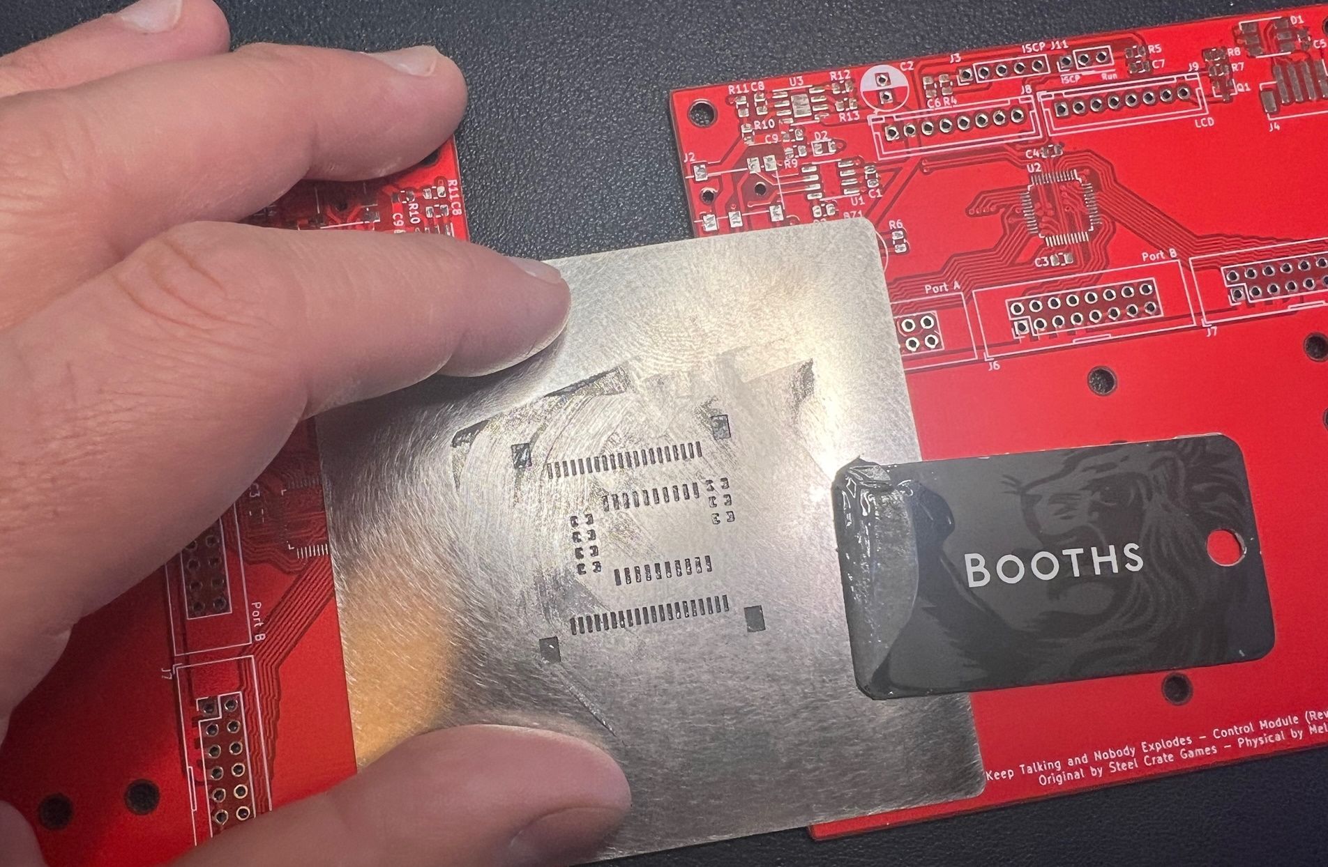
The first step is to apply the solder paste with a stencil, since moving to primarily SMD work I always purchase a stencil, it's worth the $5 to make a perfect looking PCB IMO.
I use spare PCBs to give the stencil a flat surface , then squeeze some solder paste onto the stencil and then work it through. I'm sure the thickness of solder is inconsistent compared to a machine, however it tends to work fine.
After placing all the components onto the PCB and checking orientations, the whole assembly is placed on a hot plate - this is something I built with another custom PCB, triac and a cheap chinese BGA desoldering plate.
Cook the PCB:
- 20°C->150°C over 65s
- 150°C for 120s
- 150°C->217°C over 35s
- 217°C for 60s
- 217°C->20°C over 65s.
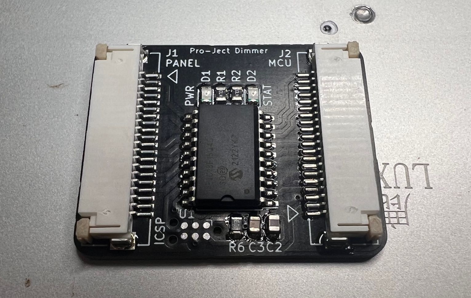
After the board has cooled down time for a visual inspection, some of components are slightly off axis or slightly uncentered, which is probably due to the age of my solder paste. It's past its suggested life and hasn't been stored exactly how it should have been.
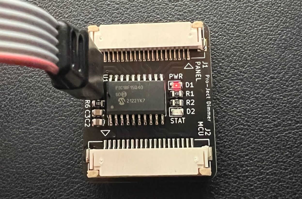
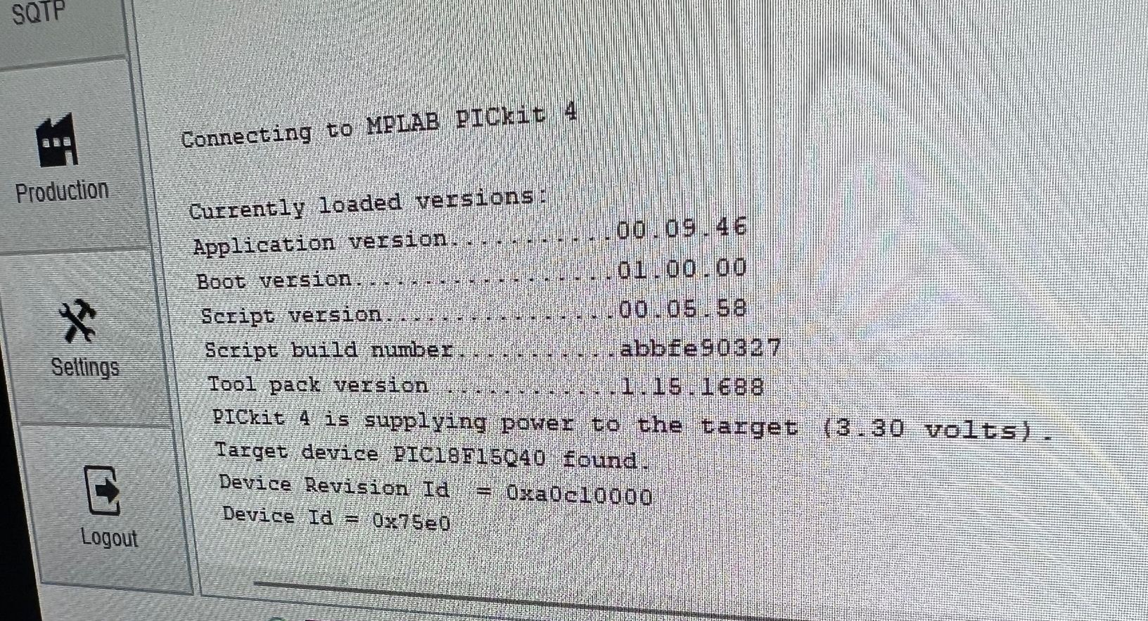
Plugging it into the PIC programmer to verify basic functionality, we at least see a power light. The LEDs are very dim with their 470 Ohm resistor, but that's fine they are just for test indications - they wont be visible once the project is complete.
The programmer can see the PIC which means the basic wiring is currect, next step is writing the firmware!